Showing posts with label Series and parallel circuits. Show all posts

Tuesday, April 6, 2010

Electronic Timer Switch - TIMER PROJECTS

Electronic Timer Switch
This electronic timer switch project is a good project to build to simulate the presence of occupants in a house. In these days when security is becoming more of a concern when no one is at home, having this device will deter the thief from breaking in. When power up, after 60 minutes, the relay will turn ON for 100 secs, OFF for the next 100 secs, and ON again for 100 secs before OFF again for the next 60 mins. This sequence will be repeated. A device such as a lamp that is connected to the relay will turn ON and OFF according to this timing.


Schematic Diagram
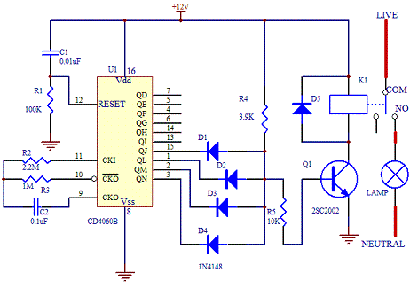
The schematic of the project is as shown below.


The core of this electronic timer switch project uses a CD4060B binary counter. The binary counter has 10 outputs and the counter are counted by configuring the oscillator. Every negative clock will trigger the counter of the IC internally.
The timing of the circuit is affected by resistor R3(1M ohm) and capacitor C2(0.1uF). By connecting the four outputs in an AND configuration, the transistor Q1 will only turn ON if all the 4 outputs are in logic "1". If any of the logic is "0", the transistor will remain OFF.
For a complete cycle, the transistor will be ON twice when the output at pin 15, QJ goes to logic "1" and "0" twice when the other outputs QL, QM and QN remain at "1". When this happen, the relay K1 will switch status accordingly. The timing of the switching can be changed by changing the resistor values R2, R3 and C2. Download the data sheet of CD4060B from Texas Instrument website for more details.
Note that since the oscillator is not using crystal, the timing may not be as accurate compared to the ideal calculation. In most cases, fine tuning the resistor and capacitor are good enough to make this project a success. To check whether the circuit is working, connect a LED in series with a 390 ohm resistor at output QD. It will flash ON and OFF as the oscillator oscillates.


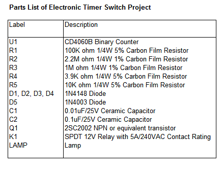
Parts List

Sunday, April 4, 2010

MUSCULAR BIO STIMULATOR

Working Of The Circuit

IC1 generates 150µSec. pulses at about 80Hz frequency. Q1 acts as a buffer and Q2 inverts the polarity of the pulses and drives the Transformer. The amplitude of the output pulses is set by P1 and approximately displayed by the brightness of LED D1. D2 protects Q2 against high voltage peaks generated by T1 inductance during switching.


Components Used

P1______________4K7 Linear Potentiometer

R1____________180K 1/4W Resistor
R2______________1K8 1/4W Resistor (see Notes)
R3______________2K2 1/4W Resistor
R4____________100R 1/4W Resistor

C1____________100nF 63V Polyester Capacitor
C2____________100µF 25V Electrolytic Capacitor

D1______________LED Red 5mm.
D2___________1N4007 1000V 1A Diode

Q1,Q2_________BC327 45V 800mA PNP Transistors

IC1____________7555 or TS555CN CMos Timer IC

T1_____________220V Primary, 12V Secondary 1.2VA Mains Transformer

SW1____________SPST Switch (Ganged with P1)

B1_____________3V Battery (two 1.5V AA or AAA cells in series etc.)

Notes

T1 is a small mains transformer 220 to 12V @ 100 or 150mA. It must be reverse connected i.e. the 12V secondary winding across Q2 Collector and negative ground, and the 220V primary winding to output electrodes.

Output voltage is about 60V positive and 150V negative but output current is so small that there is no electric-shock danger.

In any case P1 should be operated by the “patient”, starting with the knob fully counter-clockwise, then rotating it slowly clockwise until the LED starts to illuminate. Stop rotating the knob when a light itch sensation is perceived.

Best knob position is usually near the center of its range.

In some cases a greater pulse duration can be more effective in cellulite treatment. Try changing R2 to 5K6 or 10K maximum: stronger pulses will be easily perceived and the LED will shine more brightly.

Electrodes can be obtained by small metal plates connected to the output of the circuit via usual electric wire and can be taped to the skin. In some cases, moistening them with little water has proven useful.

SW1 should be ganged to P1 to avoid abrupt voltage peaks on the “patient’s” body at switch-on, but a stand alone SPST switch will work quite well, provided you remember to set P1 knob fully counter-clockwise at switch-on.

Current drawing of this circuit is about 1mA @ 3V DC .

Some commercial sets have four, six or eight output electrodes.

To obtain this you can retain the part of the circuit comprising IC1, R1, R2, C1, C2, SW1 and B1.

Other parts in the diagram (i.e. P1, R3, R4, D1, D2, Q2 & T1) can be doubled, trebled or quadrupled.

Added potentiometers and R3 series resistors must be wired in parallel and all connected across Emitter of Q1 and positive supply.

Commercial sets have frequently a built-in 30 minutes timer. For this purpose you can use the Timed Beeper.
HOW TO MAKE A TAN TIMER

This timer was designed for people wanting to get tanned but at the same time wishing to avoid an excessive exposure to sunlight.

A Rotary Switch sets the timer according to six classified Photo-types (see table).

A Photo resistor extends the preset time value according to sunlight brightness (see table).

When preset time ends, the beeper emits an intermittent signal and, to stop it, a complete switch-off of the circuit via SW2 is necessary.

Photo-type Features Exposure time
I & children Light-eyed, red-haired, light complexion, freckly 20 to 33 minutes
II Light-eyed, fair-haired, light complexion 28 to 47 minutes
III Light or brown-eyed, fair or brown-haired, light or slightly dark complexion 40 to 67 minutes
IV Dark-eyed, brown-haired, dark complexion 52 to 87 minutes
V Dark-eyed, dark-haired, olive complexion 88 to 147 minutes
VI The darkest of all 136 to 227 minutes
Note that pregnant women belong to Photo-type I


Components Used

R1_____________47K   1/4W Resistor
R2______________1M 1/4W Resistor
R3,R5_________120K 1/4W Resistors
R4____________Photo resistor (any type)

C1,C3__________10µF 25V Electrolytic Capacitors
C2____________220nF 63V Polyester Capacitor

D1,D2________1N4148 75V 150mA Diodes

IC1____________4060 14 stage ripple counter and oscillator IC
IC2____________4017 Decade counter with 10 decoded outputs IC

Q1____________BC337 45V 800mA NPN Transistor
SW1___________2 poles 6 ways Rotary Switch (see notes)
SW2___________SPST Slider Switch

BZ1___________Piezo sounder (incorporating 3KHz oscillator)

B1____________3V Battery (two 1.5V AA or AAA cells in series etc.)

NOTES

  • Needing only one time set suitable for your own skin type, the rotary switch can be replaced by hard-wired links.

  • A DIP-Switch can be used in place of the rotary type. Please pay attention to use only one switch at a time when the device is off, or the ICs could be damaged.
Your Ad Here