Showing posts with label Integrated circuit. Show all posts

Tuesday, April 6, 2010

Electronic Timer Switch - TIMER PROJECTS

Electronic Timer Switch
This electronic timer switch project is a good project to build to simulate the presence of occupants in a house. In these days when security is becoming more of a concern when no one is at home, having this device will deter the thief from breaking in. When power up, after 60 minutes, the relay will turn ON for 100 secs, OFF for the next 100 secs, and ON again for 100 secs before OFF again for the next 60 mins. This sequence will be repeated. A device such as a lamp that is connected to the relay will turn ON and OFF according to this timing.


Schematic Diagram
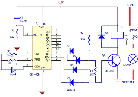
The schematic of the project is as shown below.


The core of this electronic timer switch project uses a CD4060B binary counter. The binary counter has 10 outputs and the counter are counted by configuring the oscillator. Every negative clock will trigger the counter of the IC internally.
The timing of the circuit is affected by resistor R3(1M ohm) and capacitor C2(0.1uF). By connecting the four outputs in an AND configuration, the transistor Q1 will only turn ON if all the 4 outputs are in logic "1". If any of the logic is "0", the transistor will remain OFF.
For a complete cycle, the transistor will be ON twice when the output at pin 15, QJ goes to logic "1" and "0" twice when the other outputs QL, QM and QN remain at "1". When this happen, the relay K1 will switch status accordingly. The timing of the switching can be changed by changing the resistor values R2, R3 and C2. Download the data sheet of CD4060B from Texas Instrument website for more details.
Note that since the oscillator is not using crystal, the timing may not be as accurate compared to the ideal calculation. In most cases, fine tuning the resistor and capacitor are good enough to make this project a success. To check whether the circuit is working, connect a LED in series with a 390 ohm resistor at output QD. It will flash ON and OFF as the oscillator oscillates.


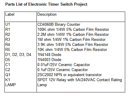
Parts List

Sunday, April 4, 2010

BASIC ELECTRONICS-TIMER CIRCUIT DESIGN

Introduction
Timer circuit has been used in many projects and there are basically 2 types that are used these days. One of them is the use of analog RC circuit where charging of the capacitor circuit determined the T(time) of the circuitry. This type of circuitry has larger tolerance and is used in applications where the T is not so critical as the T is affected by the tolerance of the RC components used.
The other is the use of crystal or ceramic resonators together with microprocessor, microcontroller or application specific integrated circuit that need higher precision T in the tolerance of up to 5 ppm (parts per million).


555 IC
One commonly used circuit is the 555 IC which is a highly stable controller capable of producing timing pulses. With a monostable operation, the T(time) delay is controlled by one external resistor and one capacitor. With an astable operation, the frequency and duty cycle are accurately controlled by two external resistors and one capacitor. The application of this integrated circuit is in the areas of PRECISION TIMING, PULSE GENERATION, TIMING DELAY GENERATION and SEQUENTIAL TIMING.
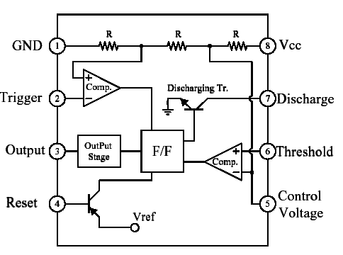
A typical 555 IC block diagram is as shown below.


Monostable Operation

Figure below shows the monostable operation of a 555 IC.


In this mode, the device generates a fixed pulse whenever the trigger voltage falls below Vcc/3. When the trigger pulse voltage applied to pin 2 falls below Vcc/3 while the its output is low, its internal flip-flop turns the discharging transistor Tr off and causes the output to become high by charging the external capacitor C1 and setting the flip-flop output at the same instant. The voltage across the external capacitor C1, VC1 increases exponentially with the time constant T=RA*C1 and reaches 2Vcc/3 at td=1.1RA*C1. Hence, capacitor C1 is charged through resistor RA. The greater the time constant RA*C1, the longer it takes for the VC1 to reach 2Vcc/3. In other words, the time constant RA*C1 controls the output pulse width. When the applied voltage to the capacitor C1 reaches 2Vcc/3, the comparator on the trigger terminal resets the flip-flop, turning the discharging transistor Tr on. At this time, C1 begins to discharge and its output goes to low.

Astable Operation


An astable operation is achieved by configuring the circuit as shown above. In the astable operation, the trigger terminal and the threshold terminal are connected so that a self-trigger is formed, operating as a multivibrator. When its output is high, its internal discharging transistor Tr turns off and the VC1 increases by exponential function with the time constant (RA+RB)*C. When the VC1, or the threshold voltage, reaches 2Vcc/3, the comparator output on the trigger terminal becomes high, resetting the F/F and causing its output to become low. This in turn turns on the discharging transistor Tr and the C1 discharges through the discharging channel formed by RB and the discharging transistor Tr. When the VC1 falls below Vcc/3, the comparator output on the trigger terminal becomes high and the timer output becomes high again. The discharging transistor Tr turns off and the VC1 rises again. The frequency of oscillation is given as below.

MUSCULAR BIO STIMULATOR

Working Of The Circuit

IC1 generates 150µSec. pulses at about 80Hz frequency. Q1 acts as a buffer and Q2 inverts the polarity of the pulses and drives the Transformer. The amplitude of the output pulses is set by P1 and approximately displayed by the brightness of LED D1. D2 protects Q2 against high voltage peaks generated by T1 inductance during switching.


Components Used

P1______________4K7 Linear Potentiometer

R1____________180K 1/4W Resistor
R2______________1K8 1/4W Resistor (see Notes)
R3______________2K2 1/4W Resistor
R4____________100R 1/4W Resistor

C1____________100nF 63V Polyester Capacitor
C2____________100µF 25V Electrolytic Capacitor

D1______________LED Red 5mm.
D2___________1N4007 1000V 1A Diode

Q1,Q2_________BC327 45V 800mA PNP Transistors

IC1____________7555 or TS555CN CMos Timer IC

T1_____________220V Primary, 12V Secondary 1.2VA Mains Transformer

SW1____________SPST Switch (Ganged with P1)

B1_____________3V Battery (two 1.5V AA or AAA cells in series etc.)

Notes

T1 is a small mains transformer 220 to 12V @ 100 or 150mA. It must be reverse connected i.e. the 12V secondary winding across Q2 Collector and negative ground, and the 220V primary winding to output electrodes.

Output voltage is about 60V positive and 150V negative but output current is so small that there is no electric-shock danger.

In any case P1 should be operated by the “patient”, starting with the knob fully counter-clockwise, then rotating it slowly clockwise until the LED starts to illuminate. Stop rotating the knob when a light itch sensation is perceived.

Best knob position is usually near the center of its range.

In some cases a greater pulse duration can be more effective in cellulite treatment. Try changing R2 to 5K6 or 10K maximum: stronger pulses will be easily perceived and the LED will shine more brightly.

Electrodes can be obtained by small metal plates connected to the output of the circuit via usual electric wire and can be taped to the skin. In some cases, moistening them with little water has proven useful.

SW1 should be ganged to P1 to avoid abrupt voltage peaks on the “patient’s” body at switch-on, but a stand alone SPST switch will work quite well, provided you remember to set P1 knob fully counter-clockwise at switch-on.

Current drawing of this circuit is about 1mA @ 3V DC .

Some commercial sets have four, six or eight output electrodes.

To obtain this you can retain the part of the circuit comprising IC1, R1, R2, C1, C2, SW1 and B1.

Other parts in the diagram (i.e. P1, R3, R4, D1, D2, Q2 & T1) can be doubled, trebled or quadrupled.

Added potentiometers and R3 series resistors must be wired in parallel and all connected across Emitter of Q1 and positive supply.

Commercial sets have frequently a built-in 30 minutes timer. For this purpose you can use the Timed Beeper.

HOW TO MAKE A TAN TIMER

This timer was designed for people wanting to get tanned but at the same time wishing to avoid an excessive exposure to sunlight.

A Rotary Switch sets the timer according to six classified Photo-types (see table).

A Photo resistor extends the preset time value according to sunlight brightness (see table).

When preset time ends, the beeper emits an intermittent signal and, to stop it, a complete switch-off of the circuit via SW2 is necessary.

Photo-type Features Exposure time
I & children Light-eyed, red-haired, light complexion, freckly 20 to 33 minutes
II Light-eyed, fair-haired, light complexion 28 to 47 minutes
III Light or brown-eyed, fair or brown-haired, light or slightly dark complexion 40 to 67 minutes
IV Dark-eyed, brown-haired, dark complexion 52 to 87 minutes
V Dark-eyed, dark-haired, olive complexion 88 to 147 minutes
VI The darkest of all 136 to 227 minutes
Note that pregnant women belong to Photo-type I


Components Used

R1_____________47K   1/4W Resistor
R2______________1M 1/4W Resistor
R3,R5_________120K 1/4W Resistors
R4____________Photo resistor (any type)

C1,C3__________10µF 25V Electrolytic Capacitors
C2____________220nF 63V Polyester Capacitor

D1,D2________1N4148 75V 150mA Diodes

IC1____________4060 14 stage ripple counter and oscillator IC
IC2____________4017 Decade counter with 10 decoded outputs IC

Q1____________BC337 45V 800mA NPN Transistor
SW1___________2 poles 6 ways Rotary Switch (see notes)
SW2___________SPST Slider Switch

BZ1___________Piezo sounder (incorporating 3KHz oscillator)

B1____________3V Battery (two 1.5V AA or AAA cells in series etc.)

NOTES

  • Needing only one time set suitable for your own skin type, the rotary switch can be replaced by hard-wired links.

  • A DIP-Switch can be used in place of the rotary type. Please pay attention to use only one switch at a time when the device is off, or the ICs could be damaged.

Electronic Sleep Inducer

Many people experienced sleeping well in natural surroundings, into a tent or a wooden hut. This fact is due not only to the healthy atmosphere but also from our unconscious ability to perceive natural Earth ’s magnetic -fields. The circuit generates this type of Geo-magnetic-fields and lets us perceive them: in this manner our brain is surrounded by an ideal environment for a sound sleep.

Features Of Sleep Inducer

* Generates a natural electromagnetic-field

* Makes easier to fall asleep

* Induces a prolonged and sound sleep without drugs

* No side effects


How To Use The Circuit

Select a timing option by means of the rotary switch SW1.

Choose 15, 30 or 60 minutes operation.

Select “Stop” or “Alternate” mode operation by means of SW2.

With SW2 closed (Stop mode operation) the electromagnetic radiation stops after the pre-set time is elapsed.

With SW2 opened (Alternate mode operation) the device operates for the pre-set time, then pauses for the same amount of time: this cycle repeats indefinitely.

Place the unit under the pillow and sleep like a log.

To reset a cycle press P1 push button.


Working Of Circuit

IC2C and IC2D generate two square waves at about 1.2 and 5 Hz respectively. These wave-forms are converted into 60µS pulses at the same frequencies by means of C5 & C6 and mixed at Q1 Base. This transistor drives the Radiator coil with a scalar series of pulses of 60µS length and 9V amplitude.

IC1, IC2A & IC2B form the timer section. C1 & R2 provide auto-reset of IC1 at switch-on. The internal oscillator of IC1 drives the 14 stage ripple counter and, after about 15 minutes, output pin 1 goes high. Pin 3 of IC2A goes low and stops IC2C & IC2D oscillation.

If SW2 is left open (Alternate mode operation), after 15 minutes pin 1 of IC1 goes low, pin 3 of IC2A goes high and oscillators are enabled again.

If SW2 is closed (Stop mode operation), the first time output pin 1 of IC1 goes high, the internal oscillator of the IC is disabled by means of D1. Therefore the circuit remains off until a reset pulse is applied to pin 12 by means of P1 or when the whole device is switched-off and then restarted.

The same thing occurs when SW1 is switched on 30 or 60 minutes positions, obviously changing time length.
IC2B drives pilot LED D2 which operates in the following three modes:

Flashes quickly and almost randomly when the Radiator coil is driven

Flashes somewhat slowly and regularly when the Radiator coil is pausing during the Alternate mode operation

Is off when the circuit auto-stops (Stop mode operation)

Components Used

R1,R5___________1K   1/4W Resistors
R2_____________10K 1/4W Resistor
R3,R6__________10M 1/4W Resistors
R4,R7___________2M2 1/4W Resistors
R8,R9___________4K7 1/4W Resistors

C1,C7__________47µF 25V Electrolytic Capacitors
C2____________100nF 63V Polyester Capacitor
C3,C4_________330nF 63V Polyester Capacitors
C5,C6__________15nF 63V Polyester Capacitors

D1,D3,D4,D5__1N4148 75V 150mA Diodes
D2______________LED (any type) (see Notes)

IC1____________4060 14 stage ripple counter and oscillator IC
IC2____________4093 Quad 2 input Schmitt NAND Gate IC

Q1____________BC327 45V 800mA PNP Transistor

L1____________Radiator coil (see Notes)

P1____________SPST Pushbutton

SW1___________2 poles 4 ways rotary switch
SW2___________SPST Slider Switch

B1____________9V PP3 Battery

Clip for PP3 Battery


Notes

L1 is obtained by winding randomly 600 turns of 0.2 mm. enameled wire on a 6 mm. diameter, 40 mm. long, steel bolt. Secure the winding with insulating tape.

Mean current drawing is about 7mA, decreasing to less than 4mA during pauses when in Alternate mode operation.

Battery life can be dramatically increased omitting LED D2 and its associated resistor R5.

Use a plastic box to enclose the circuit: metal cases can severely limit electromagnetic radiation.
Sunday, December 27, 2009

IMPROVED VERSION OF MUSCULAR BIO STIMULATOR-BIOMEDICAL PROJECTS

This circuit is a big improvement of the small Muscular Bio-Stimulator design


DOWNLOAD THE CIRCUIT DIAGRAM

COMPONENTS REQUIRED
P1_____________100K  Linear Potentiometer
P2,P3___________10K Linear Potentiometers

R1_____________560K 1/4W Resistor
R2______________68K 1/4W Resistor
R3,R4___________10K 1/4W Resistors
R5______________22K 1/4W Resistor
R6,R7____________4K7 1/4W Resistors
R8_____________330R 1/4W Resistor
R9_______________2K2 1/4W Resistor
R10____________470R 1/4W Resistor
R11_____________47R 1/4W Resistor

C1_______________1µF 63V Polyester Capacitor
C2,C3__________100nF 63V Polyester or Ceramic Capacitors
C4_____________220nF 63V Polyester Capacitor
C5_____________220µF 25V Electrolytic Capacitor

D1______________LED (Any dimension, shape and color)
D2,D3________1N4148 75V 150mA Diodes

Q1____________BC547 45V 100mA NPN Transistor
Q2,Q3_________BC327 45V 800mA PNP Transistors

IC1,IC2________7555 or TS555CN CMos Timer ICs

T1_____________230V Primary, 12V Secondary 1.2VA Mains transformer (see Notes)

SW1,SW2________SPST Toggle or Slide Switches

Notes:


  • T1 is a small mains transformer 230 to 12V @ 100 or 150mA. It must be reverse connected, i.e. the 12V secondary winding across Q3 Collector and negative ground, and the 230V primary winding to P3 and output Electrodes.

  • The circuit has been thoroughly tested, and it works nicely when supplied in the 3V - 9V range. Running on 3V supply with a 12V 1.2VA transformer it would be no more dangerous than the circuit already published. But please note that using 9V battery supply it can output 120V signals and could be very dangerous.

  • Electrodes can be obtained by small metal plates connected to the output of the circuit via usual electric wire and can be taped to the skin. In some cases, moistening them with little water has proven useful.

  • Commercial sets have frequently a built-in 30 minutes timer. For this purpose you can use the Timed Beeper the Bedside Lamp Timer or the Jogging Timer circuits available on this Website, adjusting the timing components to suit your needs.


Reblog this post [with Zemanta]
Your Ad Here