Showing posts with label Resistor. Show all posts

Tuesday, April 6, 2010

Electronic Timer Switch - TIMER PROJECTS

Electronic Timer Switch
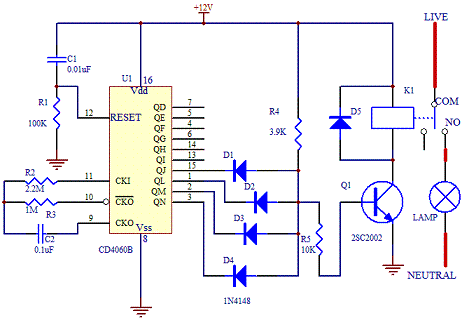
This electronic timer switch project is a good project to build to simulate the presence of occupants in a house. In these days when security is becoming more of a concern when no one is at home, having this device will deter the thief from breaking in. When power up, after 60 minutes, the relay will turn ON for 100 secs, OFF for the next 100 secs, and ON again for 100 secs before OFF again for the next 60 mins. This sequence will be repeated. A device such as a lamp that is connected to the relay will turn ON and OFF according to this timing.


Schematic Diagram
The schematic of the project is as shown below.


The core of this electronic timer switch project uses a CD4060B binary counter. The binary counter has 10 outputs and the counter are counted by configuring the oscillator. Every negative clock will trigger the counter of the IC internally.
The timing of the circuit is affected by resistor R3(1M ohm) and capacitor C2(0.1uF). By connecting the four outputs in an AND configuration, the transistor Q1 will only turn ON if all the 4 outputs are in logic "1". If any of the logic is "0", the transistor will remain OFF.
For a complete cycle, the transistor will be ON twice when the output at pin 15, QJ goes to logic "1" and "0" twice when the other outputs QL, QM and QN remain at "1". When this happen, the relay K1 will switch status accordingly. The timing of the switching can be changed by changing the resistor values R2, R3 and C2. Download the data sheet of CD4060B from Texas Instrument website for more details.
Note that since the oscillator is not using crystal, the timing may not be as accurate compared to the ideal calculation. In most cases, fine tuning the resistor and capacitor are good enough to make this project a success. To check whether the circuit is working, connect a LED in series with a 390 ohm resistor at output QD. It will flash ON and OFF as the oscillator oscillates.


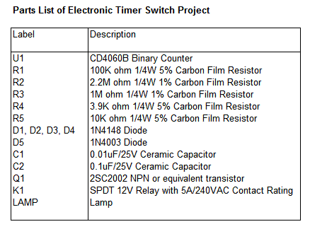
Parts List

Sunday, April 4, 2010

AUDIO WATTMETER

Here’s an easy way to measure an amplifier’s output power without trying to convert voltage to power measurements. Resistor R1 provides the load for your amplifier and should be rated at least twice the maximum amplifier power output; for example, if your amp puts out 25 watts, R1 should be rated at least 50 watts. The meter scale must be hand calibrated, and will take some time and effort, but once done it’s done for good. Remove the scale cover from meter M1 and borrow an AC variable auto-transformer, or connect a 1000 Hz signal generator to the amplifier output. Connect the output of the auto-transformer (or amplifier) to binding posts BP1 and BP2, and connect an AC voltmeter (VOM) across the binding posts. Set R2 to off – full counter-clockwise if correctly wired. Adjust the auto-transformer (or amplifier) output until the AC meter indicates 20 V rms – the voltage for 50 watts across 8 ohms. Adjust potentiometer R2 for a full scale indication on meter M1. Seal R2’s shaft with a drop of Glyptol or nail polish. Reduce the voltage across the binding posts in accordance with the table shown and mark the meter scale accordingly.


Parts List For An Audio Wattmeter

BP1, BP2 – Insulated binding posts

C1, C2 – 100 uF, 50 VDC

D1, D2, D3, D4 – Diode, HEP-134

M1 – 0.1 mA DC Meter

R1 – 8 ohm, 100 watt resistor, see text

R2 – 1500 ohm linear taper potentiometer

LOAD MATCHER

Most audio circuits transfer their maximum power at minimum distortion only when the output impedance is matched to the load impedance. But it is often necessary to connect equipment of differing impedances. For example, how do you correct an amplifier with a 600 ohm output into an amplifier with a 50 ohm input? Usually, if the 50 ohm input is connected across the amplifier with a 600 ohm output, the excessive loading caused by 50 ohms will sharply reduce the output of the 600 ohm amplifier, and will generally increase the distortion sharply.


A minimum loss pad is the device used to match a high impedance to a low impedance. Though there is always a signal level loss through a pad, the circuit shown provides the absolute minimum loss that can be obtained while providing a precise match. If the resistance values work out to odd values, such as 134 ohms, use the closest standard value. Though 5 percent tolerance resistors are suggested, almost as good performance will be obtained with 10 percent resistors.

MUSCULAR BIO STIMULATOR

Working Of The Circuit

IC1 generates 150µSec. pulses at about 80Hz frequency. Q1 acts as a buffer and Q2 inverts the polarity of the pulses and drives the Transformer. The amplitude of the output pulses is set by P1 and approximately displayed by the brightness of LED D1. D2 protects Q2 against high voltage peaks generated by T1 inductance during switching.


Components Used

P1______________4K7 Linear Potentiometer

R1____________180K 1/4W Resistor
R2______________1K8 1/4W Resistor (see Notes)
R3______________2K2 1/4W Resistor
R4____________100R 1/4W Resistor

C1____________100nF 63V Polyester Capacitor
C2____________100µF 25V Electrolytic Capacitor

D1______________LED Red 5mm.
D2___________1N4007 1000V 1A Diode

Q1,Q2_________BC327 45V 800mA PNP Transistors

IC1____________7555 or TS555CN CMos Timer IC

T1_____________220V Primary, 12V Secondary 1.2VA Mains Transformer

SW1____________SPST Switch (Ganged with P1)

B1_____________3V Battery (two 1.5V AA or AAA cells in series etc.)

Notes

T1 is a small mains transformer 220 to 12V @ 100 or 150mA. It must be reverse connected i.e. the 12V secondary winding across Q2 Collector and negative ground, and the 220V primary winding to output electrodes.

Output voltage is about 60V positive and 150V negative but output current is so small that there is no electric-shock danger.

In any case P1 should be operated by the “patient”, starting with the knob fully counter-clockwise, then rotating it slowly clockwise until the LED starts to illuminate. Stop rotating the knob when a light itch sensation is perceived.

Best knob position is usually near the center of its range.

In some cases a greater pulse duration can be more effective in cellulite treatment. Try changing R2 to 5K6 or 10K maximum: stronger pulses will be easily perceived and the LED will shine more brightly.

Electrodes can be obtained by small metal plates connected to the output of the circuit via usual electric wire and can be taped to the skin. In some cases, moistening them with little water has proven useful.

SW1 should be ganged to P1 to avoid abrupt voltage peaks on the “patient’s” body at switch-on, but a stand alone SPST switch will work quite well, provided you remember to set P1 knob fully counter-clockwise at switch-on.

Current drawing of this circuit is about 1mA @ 3V DC .

Some commercial sets have four, six or eight output electrodes.

To obtain this you can retain the part of the circuit comprising IC1, R1, R2, C1, C2, SW1 and B1.

Other parts in the diagram (i.e. P1, R3, R4, D1, D2, Q2 & T1) can be doubled, trebled or quadrupled.

Added potentiometers and R3 series resistors must be wired in parallel and all connected across Emitter of Q1 and positive supply.

Commercial sets have frequently a built-in 30 minutes timer. For this purpose you can use the Timed Beeper.
HOW TO MAKE A TAN TIMER

This timer was designed for people wanting to get tanned but at the same time wishing to avoid an excessive exposure to sunlight.

A Rotary Switch sets the timer according to six classified Photo-types (see table).

A Photo resistor extends the preset time value according to sunlight brightness (see table).

When preset time ends, the beeper emits an intermittent signal and, to stop it, a complete switch-off of the circuit via SW2 is necessary.

Photo-type Features Exposure time
I & children Light-eyed, red-haired, light complexion, freckly 20 to 33 minutes
II Light-eyed, fair-haired, light complexion 28 to 47 minutes
III Light or brown-eyed, fair or brown-haired, light or slightly dark complexion 40 to 67 minutes
IV Dark-eyed, brown-haired, dark complexion 52 to 87 minutes
V Dark-eyed, dark-haired, olive complexion 88 to 147 minutes
VI The darkest of all 136 to 227 minutes
Note that pregnant women belong to Photo-type I


Components Used

R1_____________47K   1/4W Resistor
R2______________1M 1/4W Resistor
R3,R5_________120K 1/4W Resistors
R4____________Photo resistor (any type)

C1,C3__________10µF 25V Electrolytic Capacitors
C2____________220nF 63V Polyester Capacitor

D1,D2________1N4148 75V 150mA Diodes

IC1____________4060 14 stage ripple counter and oscillator IC
IC2____________4017 Decade counter with 10 decoded outputs IC

Q1____________BC337 45V 800mA NPN Transistor
SW1___________2 poles 6 ways Rotary Switch (see notes)
SW2___________SPST Slider Switch

BZ1___________Piezo sounder (incorporating 3KHz oscillator)

B1____________3V Battery (two 1.5V AA or AAA cells in series etc.)

NOTES

  • Needing only one time set suitable for your own skin type, the rotary switch can be replaced by hard-wired links.

  • A DIP-Switch can be used in place of the rotary type. Please pay attention to use only one switch at a time when the device is off, or the ICs could be damaged.

HOW TO MAKE - MIKE DESENSITIZER

Many cassette recorders do not have a high level (aux) input; they are meant only for use with microphones. If you try to dub directly from another recorder’s “line” output, or from across the speaker, the relatively high signal level overloads the microphone input, causing severe distortion. Good dubs can be obtained by attenuating the high level signal almost 50 dB, so the attenuated signal is essentially equal to microphone level. This recorder bridging cord provides about 50 dB attenuation in a single, easy-to-handle assembly. Connect resistor R1 in series with the shielded cable hot lead. Connect the free end of R1 to recorder plug PL2 and one end of resistor R2. Fold R2 back adjacent to R1 and solder the free end to the cable shield. Loop a wire from the shield to the PL2 outside (sleeve) terminal. PL1 should match the output jack of the recorder you dub from.


Part List For Mike Desensitizer

PL1, PL2 – Plugs to match existing tape equipment Shielded cable

R1 – 100,000 ohm, 1/4 – watt resistor

R2 - 10,000 ohm, 1/4 – resistor

Sunday, December 20, 2009

HOW TO CHECK AMOUNT OF SALT IN LIQUID?-BIOMEDICAL PROJECTS

PURPOSE OF DEVICE

This circuit was designed to detect the approximate percentage of salt contained in a liquid. After careful setting it can be useful to persons needing a quick, rough indication of the salt content in liquid foods for diet purposes etc.

DOWNLOAD THE CIRCUIT DIAGRAM

WORKING OF CIRCUIT

IC1A op-amp is wired as a DC differential amplifier and its output voltage increases as the DC resistance measured across the probes decreases. In fact, fresh water has a relatively high DC resistance value that will decrease proportionally as an increasing amount of salt is added.
IC1B, IC1C and IC1D are wired as comparators and drive D5, D4 and D3 in turn, as the voltage at their inverting inputs increases. Therefore, no LED will be on when the salt content of the liquid under test is very low, yellow LED D5 will illuminate when the salt content is low, green LED D4 will illuminate if the salt content is normal and red LED D3 will illuminate if the salt content is high.
D1 and D2 are always on, as their purpose is to provide two reference voltages, thus improving circuit precision. At D2 anode a stable 3.2V supply feeds the non-inverting inputs of the comparators by means of the reference resistor chain R8, R9 and R10. The 1.6V reference voltage available at D1 anode feeds the probes and the set-up trimmer R4.
One of these two red LEDs may be used as a pilot light to show when the device is on.

HOW TO MAKE PROBES?

It was found by experiment that a good and cheap probe can be made using a 6.3mm. mono jack plug. The two plug leads are connected to the circuit input by means of a two-wire cable (a piece of screened cable works fine).
The metal body of the jack is formed by two parts of different length, separated by a black plastic ring. You should try to cover the longest part with insulating tape in order to obtain an exposed metal surface of the same length of the tip part, i.e. about 8 to 10mm. starting from the black plastic ring.
In the prototype, three tablespoons of liquid were poured into a cylindrical plastic cap of 55mm. height and 27mm. diameter, then the metal part of the jack probe was immersed in the liquid.

NOTES

  • Wait at least 30 seconds to obtain a reliable reading.

  • Wash and wipe carefully the probe after each test.

  • To setup the circuit and to obtain a more precise reading, you can use a DC voltmeter in the 10V range connected across pin #1 of IC1A and negative supply.

  • Set R4 to obtain a zero reading on the voltmeter when the probe is immersed in fresh water.

  • You may change at will the threshold voltage levels at which the LEDs illuminate by trimming R4. Vary R8 value to change D4 range and R9 value to change D5 range.

  • P1 pushbutton can be substituted by a common SPST switch.


FOR MORE INFORMATION CONTACT ADMINISTRATOR
Reblog this post [with Zemanta]
Your Ad Here