Sunday, December 27, 2009

HOW TO MAKE A MAGIC WAND?-FUN PROJECT

THIS IS A CIRCUIT OF MAKING A MAGIC WAND

I WAS JUST GETTING BORED BY BIOMEDICAL PROJECTS SO I THOUGHT I SHOULD PUT ONE FUN PROJECT HERE

IT IS AN EASY PROJECT TO MAKE MOREOVER IT WILL TEST YOUR CIRCUIT ASSEMBLY SKILLS AND HELP YOU BECOME A GOOD CIRCUIT DESIGNER

DESCRIPTION

The trick works as follows: a wand (with a magnet mounted in one end) must pass in a 1-2-3 sequence over reed switches S4 to S6 before the bulb LP1 will light. If the wand passes over reed switches S1, S2, or S3, the 1-2-3 sequence will be reset (that is, cancelled). Or, if the bulb is already burning, the activation of reed switches S1, S2, or S3 will extinguish it.

All the reed switches - S1 to S6 - are glued just beneath the surface of a 10 cm² box (Figure 2). A general purpose adhesive is suggested, so that the reed switches may later be moved if necessary. The bulb, LP1, is mounted in the centre of the box. A small PP3 9V battery may be used. The prototype box was built using balsa wood.

The wand may be waved back and forth in various motions over the box, on condition that it finally passes in the correct 1-2-3 sequence over S4 to S6 (at which point LP1 will light). This should thoroughly confuse any onlooker and make it virtually impossible for another person to repeat the correct motions with the same wand. The wand may also be lifted just high enough over reed switches S1 to S3 so as not to trigger them.

A 7.2V filament bulb, LP1, was used - instead of, say, a LED - so as not to give the trick an "electronic" appearance. The operation of the circuit is fairly simple. Three AND logic gates of a 4081 CMOS IC are employed, with gates IC1a to IC1c beingconfigured as a standard cascaded latch circuit. S1 to S3 serve as reset switches. The output at pin 10 will only switch to logic high when reed switches S4 to S6 are closed in sequence. Power transistor TR1 amplifies the output current to light bulb LP1.

Instead of a wand, a small neobdymium (super-strength) magnet may be stuck to one finger, and one's finger used in place of the wand.

In "stand-by" mode (with the bulb extinguished) the circuit will use very little current. Therefore a switch is not included in the circuit (of course, one may be added). The box may be opened and the battery simply clipped on or off.

CIRCUIT DIAGRAM

trickmagnet

HOW TO MAKE AN INFRARED SWITCH FOR THE PROJECT?-BIOMEDICAL ELECTRONICS PROJECTS

DESCRIPTION

This is a single channel (on / off) universal switch that may be used with any Infra Red remote control using 36-38kHz. (This is a very common remote handset frequency). In place of IR1 a TSOP1738 receiver may be used.

ir_switch
Notes

Any "button" of any remote control may be used to work this universal switch. The button must be pressed for about one and a half seconds (determined by R3 and C2) before the relay will operate. The circuit will remain in this state (latched) until reset. To reset, any button is pressed on the remote handset and held for a short duration.
For example, if you were watching TV, you could press and hold any button on the TV remote to trigger the circuit. In order not to change channel, you could press the button of the channel you are watching. You can connect anything to the relay, for example a lamp, but make sure that the relay contacts can handle the rated voltage and current.

Circuit Operation:
IC1 is an Infra Red module. IR modulated pulses are received and buffered by this IC. It has a standard TTL output, the output with no signal is held high by R1. A replacement for IR1 is the common TSOP1738 IR reciver. One gate of a CMOS inverter drives LED1 as a visible switching aid. Another gate buffers the signal and applies it to the time constant circuit, comprising R3,C2,R4 and D1. C2 charges via R3, and discharges via R4, D1 prevents quick discharge via the low output impedance of the CMOS buffer. If using a TSOP1738 then increase R4 to 470k.

The time taken to charge a capacitor is the product of resistance and capacitance, more commonly known as the RC time constant. At one RC a capacitor will only charge to 63% of the supply voltage. It takes 5 RC's for a capacitor to reach 99% charge. In this circuit the capacitor charge has to reach the logic threshold of the CMOS invertor. As the power supply is 5 Volts, the input threshold is around 3.6V, which takes about 3RC's or about 1.5 seconds. Once reached the inventor triggers the 555 timer and operates the flip flop. A simulation of received pulses, filtering and output pulse is shown below. Note that this is not from the actual circuit ( in which case the reconstructed pulse would be high for the duration of the 555 monostable) but only a spice simulation.

irsw_pulse

The pulses are further buffered and contain "jaggered edges" as shown above. These edges are produced by the modulated IR data, and have to be removed. This is achieved using a 555 timer wired as a monostable, IC3, having an output pulse duration R5, C4. A clean output pulse is produced to activate the bistable latch, IC4. This is a D type flip flop, built with a TTL 7474 series IC and configured as a bistable. Any version of the 7474 may be used, i.e. schottky 74LS74, high speed 74HCT74 etc. The input is applied to the clock pin, the inverted output fed back to the data input and clear and preset lines are tied to ground. For every pulse the relay will operate and latch, the next pulse will turn off the relay and so on. Note that quick turn on and off of the relay is not possible. The output pulse is set at about 2.4 seconds. and input delay by R3, C2 set about 1.5 seconds.

Parts List:
R1 3k3
R2 1k
R3 22k
R4 220k or 470k if using a TSOP1738
R5 1M
R6 3k3
B1 12 V
D1 1N4148
D2 1N4003
Q1 B109
LED1 CQX35A
IC1 IR1 available from Harrison Electronics or TSOP1838 or similar
IC2 4049
IC3 CA555
IC4 SN74HCT74 or SN74LS74
IC5 LM7805
Relay 12 Volt coil with changeover contact
C1 100u
C2 22u
C3 100n
C4 2u2
Reblog this post [with Zemanta]

AN IDEA TO BUILD LOW COST CAT SCANNER?-BIOMEDICAL IDEAS OF PROJECTS


[caption id="" align="aligncenter" width="300" caption="Image via Wikipedia"]A Philips 64 slice 'Brilliance' Scanner[/caption]


IDEA


CAT Scanning


I'd like to build a CAT Scanner. It turns out that the software isn't that hard. The algorithm is quite simple. Here are some sample images that illustrate the process. Since I don't yet have the hardware to generate x-ray slices of an object I have synthesized what an x-ray would yield if it scanned an object. These scans are then reassembled to yield the original target image.

In a real CAT Scan system the 1 dimensional slices would be taken from the horizontal row of a series of x-rays. In this demo I don't yet have the x-rays to work with so I synthesize the 1D bands from the target image that I want to regenerate. So given a target image I generate a series of 1D radial slices by rotating the target image and then averaging all values in the rows of the image. Then I rotate the slice back to the original angle.

Slices are synthesized from a 180 degree rotation of the target image.


Relative position of each scan slice

The target and four
1-dimensional sections.
The position of the
sections corresponds to
the angle of projection.

image:target.pngimage:section_4_0.png
image:section_4_3.pngimage:section_4_2.pngimage:section_4_1.png

Add (overlay) the four 1D radial sections together to get the CAT scan image at the right.

image:section_4_0.png+image:section_4_3.png+image:section_4_2.png+image:section_4_1.png = image:target_4_out.png

The resulting CAT scan is reminiscent of the target, but it is ambiguous. I found that you need at least 8 sections to get a recognizable image. The more sections you use the better. Here is a composite of 8 radial sections:

image:targetd_animated.gif image:target_8_out.png

And finally, here is 32 radial sections. This seems to be a good number for an image this resolution:

image:target_32_out.png

This simple algorithm will work with very complex images. Given a photograph I synthesized 32 1-dimensional scans and then regenerated the photograph using the CAT algorithm.


A more complex example


image:target_n.png image:target_n_out.png image:target_n_out_enhanced.png

The real world of x-rays is not so simple. In the experiments above, I actually synthesize the radial sections by averaging all the pixels in the rows. This roughly approximates how an x-ray reveals average density of a line through the target. But in the real world there can be materials inside the target that are so dense that they totally block x-ray energy. This reconstruction technique assumes that every part of a target is at least somewhat transparent. If there are parts of a target that are totally opaque even to x-rays then this will result in ambiguous, hidden sections. These hidden sections not only hide what is inside of them, but they also cause shadows that distort areas outside.

The following target is similar to the one used before except that it now has a screen added. The algorithm that synthesizes the radial sections was modified to treat any red are as totally opaque. The result is that anything inside the cup shaped screen is totally hidden. The dense area also throws off the contrast so that it is difficult to see the notch at the top of the target, but you can more or less make it out.

image:targeto.png image:targeto_out.png


Image processing


The image that results from the composite of the 1D sections has very low contrast. It is simple to expand the dynamic range of the image, but also note that the contrast is weighted towards the center. This is because the radial sections favor the center of the image. The center of the target has the most overlapping sections so the pixels near the center contribute more signal to the average. It's difficult to apply a uniform contrast enhancement over the entire image because the result will leave the edges too dark or the center too light. What is needed is contrast enhancement that will be weighted based on the distance from the center of the image.

THIS IDEA IS IMPLEMENTABLE ALREADY WORK IS GOING ON IT

IT IS TAKEN FROM INTERNET

FROM

WWW.NOAH.ORG


Reblog this post [with Zemanta]

HOW TO MAKE AN DETECTOR FOR X-RAY AND GAMMA RADIATION SOURCE?-BIOMEDICAL IMAGING PROJECTS


[caption id="" align="aligncenter" width="300" caption="Image via Wikipedia"]The danger classification sign of radioactive ...[/caption]


This describes how to build a simple detector for x-ray and gamma sources. The primary sensor is a modified photodetector. It may be built around a photodiode, phototransistor, or photodarlington. I have not tested this detector yet. An amplifier will be needed to allow measurements to be made with the detector. Unfortunately, I have been too lazy to build and test an amplifier for this. If someone wants to build me a simple amplifier that I can attach to a sensor and allow me to make measurements with a multimeter then I will send you a free sensor.

The following describes how to build the sensor. The only special component is Zinc Sulfide (ZnS) which is not too hard to order from a chemical supplier. It is fairly safe to handle.

The idea is that ZnS will glow when hit by gamma radiation. The photodector then senses this light. There are a few problems associated with this. First is calibration. How do you make quantitative measurements with this? Second is that ZnS has a long hysteresis. It will glow long after being activated by x-rays. In theory, you could calibrate the sensor and measure the decay rate of the ZnS and compensate the output based on last exposure time and known decay rate. This would require a very intelligent detector! Another possibility would be to create an array of sensors with each sensor screened by various thicknesses of lead. The relative output of the detectors should be easier to convert into a meaningful number. At this point you might as well buy a real Geiger counter or gamma ray detector.

The sensor should still be useful for qualitative x-ray detection ("Is there any radiation around here?").

1. Start with photodetector (photodiode, phototransistor, or photodarlington)


2. Coat with transparent glue


3. Dust with zinc sulfide (ZnS). Sensor is now almost ready to go.


4. Package sensor to block outside light. For example, heat shrink tubing and black electrical tape.


THIS IDEA HAS BEEN TAKEN FROM http://www.noah.org/
Reblog this post [with Zemanta]

HOW TO MAKE AN INEXPENSIVE X RAY MACHINE?-BIOMEDICAL PROJECTS


[caption id="" align="aligncenter" width="300" caption="Image via Wikipedia"]X-ray tube (scheme)[/caption]


SMALL EXCERPT

From an old radio tube, some copper wire, and other inexpensive materials — total cost: roughly $20 — you can construct an X-ray machine that will make good pictures through an inch of wood. SAFETY MEASURES THAT YOU MUST OBSERVE. Notes on Röntgen's invention. Highlights of X-ray theory.

ALL THIS WAS DIFFICULT TO BE PUBLISHED AS IMAGES  WERE HEAY SO I DECIDE TO MAKE A PDF FOR THE CONVENIENCE OF THE USER

ALL THE CREDITS MUST GO TO THE DEVELOPER OF THIS MACHINE

WHAT AN AMAZING IDEA???

DOWNLOAD THE COMPLETE PROJECT CONCEPT FROM HERE

CONCEPT AND PROJECT

Reblog this post [with Zemanta]

HOW TO MAKE A HEARING AID?


[caption id="" align="aligncenter" width="254" caption="Image via Wikipedia"]Image illustrating the different types of hear...[/caption]


DESCRIPTION

Commercially available hearing aids are quite costly. Here is an inexpensive hearing aid circuit that uses just four transistors and a few passive components.

On moving power switch S to ‘on’ position, the condenser microphone detects the

sound signal, which is amplified by transistors T1 and T2. Now the amplified signal

passes through coupling capacitor C3 to the base of transistor T3. The signal is further

amplified by pnp transistor T4 to drive a low impedance earphone. Capacitors C4 and C5

are the power supply decoupling capacitors.

The circuit can be easily assembled on a small, general-purpose PCB or a Vero board. It operates off a 3V DC supply. For this, you may use two small 1.5V cells. Keep switch S to ‘off’ state when the circuit is not in use. To increase the sensitivity of the condenser microphone house it inside a small tube.

This circuit costs around Rs 65.

DOWNLOAD THE CIRCUIT DIAGRAM
Reblog this post [with Zemanta]

HOW TO MAKE A METAL DETECTOR?-ELECTRONICS PROJECT

ABOUT

A single chip metal detecor with a range of a few inches. This is useful for decting nails or screws in walls and floors, or for locating buried mains cable.

CIRCUIT DIAGRAM

metaldetector

HOW TO MAKE A HEART RATE SENSOR?-BIOMEDICAL PROJECTS

I HAVE  ARRANGED A SCHEMATIC ABOUT MAKING A HEART RATE SENSOR

DOWNLOAD THE CIRCUIT DIAGRAM FOR THE HEART RATE SENSOR

DOWNLOAD

SOMETHING MORE

Here is the inside of the light reflectance sensor (top) and a schematic drawing of it's circuitry (bottom). First, carefully remove the phototransistor as shown. Then, attach the three wires that we will connect to the heart sensor (show in bright yellow).

Hint: if you leave the leads from the phototransistor when you cut it off, you can attach the two corresponding wires directly to them, rather than to the circuit board itself.


Reblog this post [with Zemanta]

HOW TO MAKE HEART RATE MONITOR RECEIVER By RICK MOLL?-BIOMEDICAL PROJECTS

IDEA

Commercial HRM transmitters are available from several manufacturers. The HRM receiver


described here allows these transmitters to be interfaced to a small microcontroller or PC.


The HRM receiver is built on a 2.5 x 1.8 inch printed circuit board. It can be interfaced to just about any microcontroller that has an analog input. It will operate from the same 5V supply that powers the microcontroller. With each heart beat signal it receives from a wireless HRM transmitter, it outputs an analog pulse. These pulses are typically sampled with a microcontroller ADC port.

HRM Transmitter

This wireless HRM transmitter was manufactured by Polar, who claims to be the world's leading producer of wireless HRM equipment. Cardiosport and Sports Instruments manufacture similar equipment.


These transmitters are worn around the chest and generate a 5kHz magnetic pulse with each heart beat they detect. The transmitted magnetic signals are fairly weak, but typically have a range of over 3 feet.

These HRM transmitters can be purchased for as little as $40 (USD), or along with a no frills wrist style receiver for around $50 (USD).

circuit description

schematic

code


for any further querry contact the administrator


Reblog this post [with Zemanta]

HOW TO MAKE INFRARED HEART PULSE MONITOR?-BIOMEDICAL PROJECTS


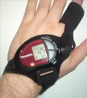
[caption id="" align="aligncenter" width="300" caption="Image via Wikipedia"]Photo of a strapless heart rate monitor[/caption]


I HAVE MADE A CIRCUIT ON HEART PULSE MONITOR

This circuit is given at the bottom

ABSTRACT FROM A PATENT ON HEART PULSE MONITOR

The invention herein described is intended to provide the user with a reliable heart rate monitor that is a completely self contained unit and is capable of providing accurate readings while the wearer is moving about. The use of piezoelectric sensing elements eliminates the power drain caused by LEDs and similar devices. The sensing element mounting means disclosed herein is devised to greatly reduce the noise introduced into the pulse signal by body motion. The use of optical sensors in a staring mode and optical sensors in a pulsed mode is also presented. The effects of noise are further reduced by employing digital signal processing algorithms to find the heart pulse intermixed with noise signals and present the heart pulse rate in beats per minute on a display. The resulting device permits the visual monitoring of the heart pulse rate in a human body in a consistent, error-free manner.

DOWNLOAD THIS PATENT FROM HERE

About the heart pulse monitor circuit

DOWNLOAD THE CIRCUIT DIAGRAM

THIS CIRCUIT DIAGRAM IS SELF EXPLANATORY

IF ANYONE NEEDS HELP THEN CONTACT THE ADMINISTRATOR
Reblog this post [with Zemanta]

IMPROVED VERSION OF MUSCULAR BIO STIMULATOR-BIOMEDICAL PROJECTS

This circuit is a big improvement of the small Muscular Bio-Stimulator design


DOWNLOAD THE CIRCUIT DIAGRAM

COMPONENTS REQUIRED
P1_____________100K  Linear Potentiometer
P2,P3___________10K Linear Potentiometers

R1_____________560K 1/4W Resistor
R2______________68K 1/4W Resistor
R3,R4___________10K 1/4W Resistors
R5______________22K 1/4W Resistor
R6,R7____________4K7 1/4W Resistors
R8_____________330R 1/4W Resistor
R9_______________2K2 1/4W Resistor
R10____________470R 1/4W Resistor
R11_____________47R 1/4W Resistor

C1_______________1µF 63V Polyester Capacitor
C2,C3__________100nF 63V Polyester or Ceramic Capacitors
C4_____________220nF 63V Polyester Capacitor
C5_____________220µF 25V Electrolytic Capacitor

D1______________LED (Any dimension, shape and color)
D2,D3________1N4148 75V 150mA Diodes

Q1____________BC547 45V 100mA NPN Transistor
Q2,Q3_________BC327 45V 800mA PNP Transistors

IC1,IC2________7555 or TS555CN CMos Timer ICs

T1_____________230V Primary, 12V Secondary 1.2VA Mains transformer (see Notes)

SW1,SW2________SPST Toggle or Slide Switches

Notes:


  • T1 is a small mains transformer 230 to 12V @ 100 or 150mA. It must be reverse connected, i.e. the 12V secondary winding across Q3 Collector and negative ground, and the 230V primary winding to P3 and output Electrodes.

  • The circuit has been thoroughly tested, and it works nicely when supplied in the 3V - 9V range. Running on 3V supply with a 12V 1.2VA transformer it would be no more dangerous than the circuit already published. But please note that using 9V battery supply it can output 120V signals and could be very dangerous.

  • Electrodes can be obtained by small metal plates connected to the output of the circuit via usual electric wire and can be taped to the skin. In some cases, moistening them with little water has proven useful.

  • Commercial sets have frequently a built-in 30 minutes timer. For this purpose you can use the Timed Beeper the Bedside Lamp Timer or the Jogging Timer circuits available on this Website, adjusting the timing components to suit your needs.


Reblog this post [with Zemanta]

Friday, December 25, 2009

HOW TO MAKE A DEVICE IN WHICH EYE CONTROLS WRITING?-BIOMEDICAL PROJECTS

HOW TO MAKE ULTRASONIC PAIN FIELD GENERATOR-BIOMEDICAL PROJECTS

ABOUT THIS PROJECT

"THIS PROJECT IS DANGEROUS HANDLE WITH CARE"

This pain field generator is an ultrasonic device which can be used other than laboratory in the field of animal pests and rodent control,certain rodents if get caught in it will go freenzy causing them brain hemmoraging,vomiting,decreases in mating urges,slowing down of metabolic functions,

all of this can be done just done by controlling the frequency in particular for a particular species

They are mainly used in food storage areas,waste areas or where animals like rat are a big problem

below is a document which gives a detail about the project

may you may be able to convert into a marvellous discovery for human beings

ADMINISTRATOR HOLDS NO RESPONSIBILITY IF ANYTHING GOES WRONG

DOWNLOAD THIS PROJECT FROM HERE

DOWNLOAD PROJECT

REFERENCES

GO TO SITE

Thursday, December 24, 2009

16 CHANNEL BRAIN TISSUE STIMULATOR-BIOMEDICAL PROJECTS


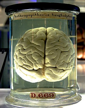
[caption id="" align="aligncenter" width="300" caption="Image via Wikipedia"]A chimpanzee brain at the Science Museum London[/caption]


SUMMARY OF PROJECT

The pathways of brain circuitry can be studied by delivering current impulses to
brain tissue and observing the tissue response.  The goal of this project is To
develop a current source to be used for in vitro stimulation of rodent neural
tissue.
The current source must deliver independently controlled currents to 16
separate electrodes on a 16 microelectrode array.  In addition, the currents must
be controllable via TTL computer logic and have a short response time to the
initial signal.  The design described in this report uses a transformer to supply a
large isolated voltage to 16 circuits which will convert the voltage to an
appropriate current.  The current on each channel will be controlled by a
potentiometer which varies the magnitude of the impulse received from a TTL
computer signal.  When the computer program supplies an impulse, a
corresponding square wave current pulse will be applied to the tissue.

DOWNLOAD THE PROJECT FROM HERE


LINK1


Reblog this post [with Zemanta]

HOW TO MAKE AN IMPEDANCE CARDIOGRAPH-BIOMEDICAL PROJECTS

IMPEDNC CARDIOGRAPHY

PROBLEM STATEMENT

Impedance cardiography is a medical procedure utilized in order to noninvasively
analyze and depict the flow of blood through the body.

Traditionally, four electrodes are attached to the body, two on the neck and two on the chest, which take beat by beat measurements of blood volume and velocity changes in the aorta.

However, this system suffers from degrees of inaccuracy, possibly due to the fact that the electrodes are placed too far from the heart.

As a result, it is our collective goal to design an accurate,
reusable, and spatially specific impedance cardiograph system that ensures accurate and
reliable readings.


DOWNLOAD THE COMPLETE PROJECT FROM HERE

LINK 1


FINGER PLETHSYMOGRAPH TO MEASURE BLOOD RESISTIVITY-BIOMEDICAL PROJECTS

SUMMARY ABOUT THE PROJECT

Impedance plethysmography can be used to measure arterial volume change that occurs with propagation of the blood pressure pulse in a limb segment. For this measurement, we assume a constant value of blood resistivity.

However, blood resistivity may change under both physiological and pathological conditions. Use of an impedance plethysmograph on a finger immersed in a saline filled beaker may yield a method for determining this change in blood resistivity.

This may develop into a method that diabetics can use to measure glucose levels non-
invasively.  The goal of our project is to design a finger plethysmograph to measure blood resistivity.

PROBLEM STATEMENT
Our goal is to design a finger plethysmograph to measure blood resistivity.  In order to
accomplish this, we will need to design and build a data acquisition device to acquire the signal
from the finger.

The device should mechanically immobilize the test subjects’ finger such that motion artifacts are kept to a minimum.

This device should be able to detect the electrical potential (voltage) change across the finger so that the change in resistance may be determined.
It should be able to detect the velocity-dependent change in blood resistivity due to arterial blood pulsations.
In addition, we will need to build an electrical circuit to perform signal processing and
analysis.  This circuit should be capable of rectifying the alternating current (AC) signal from the finger data acquisition device and modulate it into a direct current (DC) signal to be analyzed.  The circuit should be capable of discerning or visually displaying the voltage changes caused by correlated changes in blood resistivity.

As an added feature, this circuit may contain an automatic reset function capable of adjusting one of the differential amplifier inputs to that of the output from the data acquisition (finger holder) device.

This will allow the device to easily accommodate fingers having different electrical resistances and will prevent having to manually adjust voltages using a potentiometer to match independences with each new test subject or finger position.

FPDOWNLOAD THE COMPLETE PROJECT REPORT FROM HERE

LINK 1


Reblog this post [with Zemanta]
Your Ad Here